I just received the batteries and charger from Bob Burns at Thunder Power. He also sent me 2 T-shirts and a bunch of stickers. Thanks Bob! I am going to post some updates to my car in the next couple days.
Wednesday, February 28, 2007
Thunder Power is here!
I just received the batteries and charger from Bob Burns at Thunder Power. He also sent me 2 T-shirts and a bunch of stickers. Thanks Bob! I am going to post some updates to my car in the next couple days.
Tuesday, February 27, 2007
Make a donation
If you would like to be part of this project, go ahead and click on the button to the right. You can use an existing Paypal account, setup a new one or pay with a credit card. You can enter an amount you like. I will keep track of everyone who donates and place their names on my car.
Wednesday, February 21, 2007
Design update
 I have updated my model to reflect some changes in the design. The car is now based on a NEU 2215 1.5Y motor. I wasn't getting any luck from Lehner and this motor also costs a bit less for about the same amount of power I was looking at before. I also narrowed the chassis down from 200mm to 180mm. I relocated the receiver to the front of the car to get it away from the electronics to help with interference. I removed the gyro and rudder servo.
Friday, February 16, 2007
We have Thunder Power!
 Thunder Power has generously donated some of their batteries and will be the sole provider of power for my car.
Sponsors so far:
Batteries: Bob Burns at Thunder Power will supply the TP3300-4SX 14.8V 3300mAh 4-Cell packs, a charge and a balancer. These are the best Li-Pos around. Thanks Bob.
CNC machining: Aggressive Technologies has lent his CNC machining skills. Darren at Aggressive Technologies also mentioned that he knows pro driver Paul LeMieux. Paul Lemieux is one of the best touring car drivers in the world and has an impressive list of wins in the last few years. Hey Paul, do you want to drive this thing for me? Everyone knows that I can't drive. Plus, if you do wreck the car, I won't be responsible!
Carbon Fiber: I have been in contact with Matt at Ballistic Technology. He has done some excellent work on RC cars as well as top quality RC helicopters. He might have some extra carbon fiber to loan me. I have also contacted Wes at Out Front Frames. He has services available to make the chassis components.
Sponsors still needed:
Motor: Lehner can become a sponsor or someone can donate a Lehner 3060/7 motor for this car.
Speed Control: I have emailed Castle Creations asking if they would like to sponsor me. I am looking for a Castle Creations HV-110. If anyone has one available or would like to donate one, please contact me: nick.maslowski@gmail.com
Monday, February 12, 2007
200 mph prototype- Looking for sponsors to help build
Design Update-3/9/07
Design Update-3/1/07
Design Update-2/21/07
This is a project I have been working on for a couple months. I have been designing this on CATIA V5. It is electric and based on a RC10L3. My design uses a 3mm thick piece of carbon fiber for the main chassis and for the various rear suspension pieces. The motor is a Lehner 3060/7 which has a 1000 rpm/v rating. It uses 8s1p Li-Po for a total of 29.6 volts. This equates to a theoretical maximum rpm of 29,600 rpm with no load. The rear wheels are 79mm in diameter. At theoretical max rpm with no transmission or gear reduction (it is direct drive), the linear velocity is 273.87 mph. It will never reach that speed due to the high aerodynamic drag it will encounter. Wind tunnel testing needs to be done to calculate its drag coefficient. The car will also use a gyro for lateral stability. It will be used in a similar way as a gyro is used in helicopters and planes. If there is a gust of wind that forces the car to move in one direction, the gyro will sense this and compensate by sending a signal to the rudder servo. The rudder will move in a direction to counter the effect of the wind gust. It will help keep the model pointed in a straight line by dampening the effects of a cross wind. This is known as a heading hold mode on gyros.
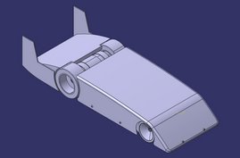
 This view shows the components with the body removed. The tail booms and vertical stabalizers have been left in place.
 More views of the X2 prototype
 CATIA Model
This is still a work in progress as 90% of the design work is done. As you can see from my model, I don't have many of the smaller connecting hardware modelled. I also didn't fully model the parts that I knew would be using off the shelf. The idea of this initial model was to size up the components and to see if the design would be possible. All of the components needed to build this are modelled and fully detailed with dimensions. I have all the blueprints to build this (the drawing of the chassis is shown below as an example). After completing most of the modelling I can see that this will be possible except for one thing: cost.
 Example of the chassis drawing with full dimensioning.
 Quick power required estimates (courtesy of Gordon Freeman)
The problem is the cost of making some of these parts. The chassis parts aren't too expensive to produce. The expensive parts to be machined are the hubs used to attach the motor to the wheels. I also need the motor clamps to be machined. Initial pricing quotes for the CNC machining on the hubs is around $400... each! The motor costs around $700. All the suspension components can be taken from an RC10L3/4. I would like to make this car happen but I need help. If anyone could donate materials or skills in making this car, that would be awesome. If you know how to machine or can donate some pieces of 3mm carbon fiber, you'll be able to see your components be put together on this record setting car. Everyone who has helped make this happen can have a spot on the body of the vehicle for some much appreciated thanks and ad space (just like NASCAR)! If you would like to donate skills, email me at nick.maslowski@gmail.com. I can send you the specs and drawings for the components that you have the skills to make. Then I'll take your finished product and put it on the car. I will keep a detailed step by step construction process as I get the parts and post it here on this website. I wish I didn't have to beg from others, but I don't have the funds and would love to see something like this car built and run. I would like to have it complete in time for RC Car Action's Worlds Fastest RC Car contest on July 28, 2007.
Updated 2/16/07
Sponsors so far:
Batteries: Bob Burns at Thunder Power will supply the TP3300-4SX 14.8V 3300mAh 4-Cell packs, a charge and a balancer. These are the best Li-Pos around. Thanks Bob.
CNC machining: Aggressive Technologies has lent his CNC machining skills. Darren at Aggressive Technologies also mentioned that he knows pro driver Paul LeMieux. Paul Lemieux is one of the best touring car drivers in the world and has an impressive list of wins in the last few years. Hey Paul, do you want to drive this thing for me? Everyone knows that I can't drive. Plus, if you do wreck the car, I won't be responsible!
Carbon Fiber: I have been in contact with Matt at Ballistic Technology. He has done some excellent work on RC cars as well as top quality RC helicopters. He might have some extra carbon fiber to loan me. I have also contacted Wes at Out Front Frames. He has services available to make the chassis components.
Sponsors still needed:
Motor: Lehner can become a sponsor or someone can donate a Lehner 3060/7 motor for this car.
Speed Control: I have emailed Castle Creations asking if they would like to sponsor me. I am looking for a Castle Creations HV-110. If anyone has one available or would like to donate one, please contact me: nick.maslowski@gmail.com
Design Update-3/1/07
Design Update-2/21/07
This is a project I have been working on for a couple months. I have been designing this on CATIA V5. It is electric and based on a RC10L3. My design uses a 3mm thick piece of carbon fiber for the main chassis and for the various rear suspension pieces. The motor is a Lehner 3060/7 which has a 1000 rpm/v rating. It uses 8s1p Li-Po for a total of 29.6 volts. This equates to a theoretical maximum rpm of 29,600 rpm with no load. The rear wheels are 79mm in diameter. At theoretical max rpm with no transmission or gear reduction (it is direct drive), the linear velocity is 273.87 mph. It will never reach that speed due to the high aerodynamic drag it will encounter. Wind tunnel testing needs to be done to calculate its drag coefficient. The car will also use a gyro for lateral stability. It will be used in a similar way as a gyro is used in helicopters and planes. If there is a gust of wind that forces the car to move in one direction, the gyro will sense this and compensate by sending a signal to the rudder servo. The rudder will move in a direction to counter the effect of the wind gust. It will help keep the model pointed in a straight line by dampening the effects of a cross wind. This is known as a heading hold mode on gyros.
 This view shows the components with the body removed. The tail booms and vertical stabalizers have been left in place.
  More views of the X2 prototype
 CATIA Model
This is still a work in progress as 90% of the design work is done. As you can see from my model, I don't have many of the smaller connecting hardware modelled. I also didn't fully model the parts that I knew would be using off the shelf. The idea of this initial model was to size up the components and to see if the design would be possible. All of the components needed to build this are modelled and fully detailed with dimensions. I have all the blueprints to build this (the drawing of the chassis is shown below as an example). After completing most of the modelling I can see that this will be possible except for one thing: cost.
 Example of the chassis drawing with full dimensioning.
  Quick power required estimates (courtesy of Gordon Freeman)
The problem is the cost of making some of these parts. The chassis parts aren't too expensive to produce. The expensive parts to be machined are the hubs used to attach the motor to the wheels. I also need the motor clamps to be machined. Initial pricing quotes for the CNC machining on the hubs is around $400... each! The motor costs around $700. All the suspension components can be taken from an RC10L3/4. I would like to make this car happen but I need help. If anyone could donate materials or skills in making this car, that would be awesome. If you know how to machine or can donate some pieces of 3mm carbon fiber, you'll be able to see your components be put together on this record setting car. Everyone who has helped make this happen can have a spot on the body of the vehicle for some much appreciated thanks and ad space (just like NASCAR)! If you would like to donate skills, email me at nick.maslowski@gmail.com. I can send you the specs and drawings for the components that you have the skills to make. Then I'll take your finished product and put it on the car. I will keep a detailed step by step construction process as I get the parts and post it here on this website. I wish I didn't have to beg from others, but I don't have the funds and would love to see something like this car built and run. I would like to have it complete in time for RC Car Action's Worlds Fastest RC Car contest on July 28, 2007.
Updated 2/16/07
Sponsors so far:
Batteries: Bob Burns at Thunder Power will supply the TP3300-4SX 14.8V 3300mAh 4-Cell packs, a charge and a balancer. These are the best Li-Pos around. Thanks Bob.
CNC machining: Aggressive Technologies has lent his CNC machining skills. Darren at Aggressive Technologies also mentioned that he knows pro driver Paul LeMieux. Paul Lemieux is one of the best touring car drivers in the world and has an impressive list of wins in the last few years. Hey Paul, do you want to drive this thing for me? Everyone knows that I can't drive. Plus, if you do wreck the car, I won't be responsible!
Carbon Fiber: I have been in contact with Matt at Ballistic Technology. He has done some excellent work on RC cars as well as top quality RC helicopters. He might have some extra carbon fiber to loan me. I have also contacted Wes at Out Front Frames. He has services available to make the chassis components.
Sponsors still needed:
Motor: Lehner can become a sponsor or someone can donate a Lehner 3060/7 motor for this car.
Speed Control: I have emailed Castle Creations asking if they would like to sponsor me. I am looking for a Castle Creations HV-110. If anyone has one available or would like to donate one, please contact me: nick.maslowski@gmail.com
Tuesday, February 6, 2007
Video: wind tunnel testing
In college, I wanted to do something interesting for my senior project. I decided I wanted to look at different types of air foil shapes to replace the standard wings that have been used in oval racing. My goal was to find a design that was much more efficient at producing downforce. I tested 4 different wing configurations at 3 different speeds from 0 to 112 ft/s (77 mph). Here is a link to my full report (PDF).
This is a video of the car being tested from 0 to 80 mph. There is an airspeed indicator in the upper right of the screen. As it reaches 80 mph you can see how much the wing bends down from the force of the air. It also starts to flutter at those high speeds (its hard to see, but its starts shaking at about 60 mph)
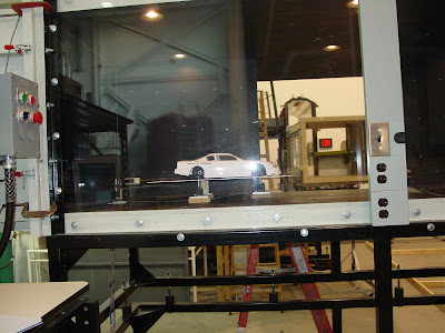 Car ready to be tested in tunnel
 This shows the setup used to measure the loads. There is one load cell for the front end of the car and one load cell for the rear of the car. There is a force trasducer to also measure drag. The load cells and force transducers work by measuring resistance in a strain gauge located in the load cells and force transducers. A voltage is applied to the strain gauge and current and resistance is measured. As a load is applied the length of the conductor changes and its resistance changes. The changes in resistance are measured and then the actual load applied can be calculated. I could only measure half the downforce applied to the rear end because I only had one force transducer. The graphs shown below only represent half the total downforce on the rear axle. It was unfortunate to have many problems with getting accurate data from the front force transducer. I was unable to get any data loads from the front axle of the car. I would have liked to compare the front to rear downforce.
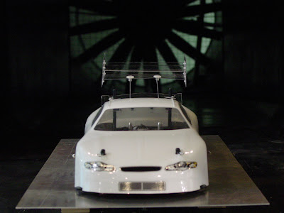 Traditional wing and spoiler installed
 Anderson airfoil
 Anderson airfoil cross section
 NACA 9509 airfoil
 NACA 9509 airfoil cross section
 This is the shape of the wing with zero windspeed.
 Severe wing deformation at 80 mph
 Drag vs. Speed.
 Downforce vs. Speed. You can see that the baseline body (no spoiler or wing) actually creates lift. This can be terribly bad at high speeds. Even using a spoiler reduces lift significantly. Also, you can see the standard wings downforce falls off dramatically above 50 mph. This is because of the deformation that is caused from the high speed. The lexan material is not able to keep the wings shape and causes it to lose its effectiveness.
This is a link to the facilties I used at Iowa State. I used the Bill James Wind Tunnel. Its an open circuit tunnel for aerodynamic testing (3.0 ft wide by 2.5 ft high section) with 180 mph wind speed capability.


This is a video of the car being tested from 0 to 80 mph. There is an airspeed indicator in the upper right of the screen. As it reaches 80 mph you can see how much the wing bends down from the force of the air. It also starts to flutter at those high speeds (its hard to see, but its starts shaking at about 60 mph)
 Car ready to be tested in tunnel
 This shows the setup used to measure the loads. There is one load cell for the front end of the car and one load cell for the rear of the car. There is a force trasducer to also measure drag. The load cells and force transducers work by measuring resistance in a strain gauge located in the load cells and force transducers. A voltage is applied to the strain gauge and current and resistance is measured. As a load is applied the length of the conductor changes and its resistance changes. The changes in resistance are measured and then the actual load applied can be calculated. I could only measure half the downforce applied to the rear end because I only had one force transducer. The graphs shown below only represent half the total downforce on the rear axle. It was unfortunate to have many problems with getting accurate data from the front force transducer. I was unable to get any data loads from the front axle of the car. I would have liked to compare the front to rear downforce.
  Traditional wing and spoiler installed
 Anderson airfoil
 Anderson airfoil cross section
 NACA 9509 airfoil
 NACA 9509 airfoil cross section
 This is the shape of the wing with zero windspeed.
  Severe wing deformation at 80 mph
 Drag vs. Speed.
 Downforce vs. Speed. You can see that the baseline body (no spoiler or wing) actually creates lift. This can be terribly bad at high speeds. Even using a spoiler reduces lift significantly. Also, you can see the standard wings downforce falls off dramatically above 50 mph. This is because of the deformation that is caused from the high speed. The lexan material is not able to keep the wings shape and causes it to lose its effectiveness.
This is a link to the facilties I used at Iowa State. I used the Bill James Wind Tunnel. Its an open circuit tunnel for aerodynamic testing (3.0 ft wide by 2.5 ft high section) with 180 mph wind speed capability.
Worlds Fastest RC car challenge Saturday July 28, 2007
WFRCCC II: Saturday, July 28, 2007
From Pete V. of RC Car Action:
"Worlds Fastest" rules
THE VEHICLES
1. Wheel-driven vehicles only. Vehicles powered by thrust (jet, rocket, propeller, etc.) are not allowed. Turbine power is allowed only if the turbine is used to drive the wheels, not for thrust.
2. Vehicles may be powered by engine(s) or motor(s) of any number and configuration.
3. Vehicles may be any weight, with any chassis configuration and any number of wheels—but the completed vehicle may not exceed 40 inches (1016mm) in length.
4. All vehicles must use commercially available FM radio gear with a functioning fail-safe system set to apply full brake in the event of signal loss or interference.
5. Vehicles are not required to look like any type of "real" car or truck, but all entries must have some type of 3-dimensional "cockpit area" with windows (clear or painted). It's OK if your car looks like a space ship as long as it appears to have a place for a guy to sit.
6. The vehicle must remain operable after its speed runs. Sacrificial motors or power systems that are inoperable after a run are not permitted.
7. Drivers must operate their vehicles from a fixed position. Chase cars are not permitted.
8. Drivers or teams may enter as many cars as they like.
THE ENTRANTS
Entrants will be divided into three classes: Manufacturer Team, Independent Team and Individual.
MANUFACTURER TEAM: entries fielded by RC companies will run in the Manufacturer Team class.
INDEPENDANT TEAM: if the entered vehicle is the collaboration of three or more individuals operating without the support of a manufacturer, it will run in the Independent Team class. High school shop teams, university engineering departments, RC clubs ... this is your class!
INDIVIDUAL: any vehicle entered by a single person will run in the Individual class.
THE WINNER
Each vehicle will be given three attempts to make its fastest run. The vehicle with the absolute highest peak speed will be declared the overall winner, and separate awards will be given to the fastest vehicles in the Manufacturer, Independent and Individual classes.
Special awards will also be given for "Most Innovative Design," "Fastest-Looking", "Fastest Production Car" (for vehicles that are still recognizable as production-based cars and trucks), "Fastest Engine-Powered Car" and "Fastest Electric Car." We may also make up some awards at the event, based on the type of vehicle that show up (Fastest Monster Truck? Fastest Motorcycle? Surprise us!). It's a top-speed contest, but we'll also reward creativity and originality; we don't want every car to be a rail with 20 cells.
From Pete V. of RC Car Action:
Same rules as last year, but we'll also be posting new rules soon as to what constitutes a Mini, a Monster Truck, a Motorcycle etc. Again, ANYTHING that follows the essential rules (wheel-driven, 40" long or less) will be allowed to run. But if you stretch an RC18T to a 12" wheelbase and run 1/10 scale touring car tires in it, you can't say it's running in the "mini" class.
We also want to avoid endless sub-classes (for example, we won't have Monster Truck nitro, Monster Truck brushed, Monster Truck brushless, Monster Truck 1/8, Monster Truck 1/10--there will just be "Monster Truck")
"Worlds Fastest" rules
THE VEHICLES
1. Wheel-driven vehicles only. Vehicles powered by thrust (jet, rocket, propeller, etc.) are not allowed. Turbine power is allowed only if the turbine is used to drive the wheels, not for thrust.
2. Vehicles may be powered by engine(s) or motor(s) of any number and configuration.
3. Vehicles may be any weight, with any chassis configuration and any number of wheels—but the completed vehicle may not exceed 40 inches (1016mm) in length.
4. All vehicles must use commercially available FM radio gear with a functioning fail-safe system set to apply full brake in the event of signal loss or interference.
5. Vehicles are not required to look like any type of "real" car or truck, but all entries must have some type of 3-dimensional "cockpit area" with windows (clear or painted). It's OK if your car looks like a space ship as long as it appears to have a place for a guy to sit.
6. The vehicle must remain operable after its speed runs. Sacrificial motors or power systems that are inoperable after a run are not permitted.
7. Drivers must operate their vehicles from a fixed position. Chase cars are not permitted.
8. Drivers or teams may enter as many cars as they like.
THE ENTRANTS
Entrants will be divided into three classes: Manufacturer Team, Independent Team and Individual.
MANUFACTURER TEAM: entries fielded by RC companies will run in the Manufacturer Team class.
INDEPENDANT TEAM: if the entered vehicle is the collaboration of three or more individuals operating without the support of a manufacturer, it will run in the Independent Team class. High school shop teams, university engineering departments, RC clubs ... this is your class!
INDIVIDUAL: any vehicle entered by a single person will run in the Individual class.
THE WINNER
Each vehicle will be given three attempts to make its fastest run. The vehicle with the absolute highest peak speed will be declared the overall winner, and separate awards will be given to the fastest vehicles in the Manufacturer, Independent and Individual classes.
Special awards will also be given for "Most Innovative Design," "Fastest-Looking", "Fastest Production Car" (for vehicles that are still recognizable as production-based cars and trucks), "Fastest Engine-Powered Car" and "Fastest Electric Car." We may also make up some awards at the event, based on the type of vehicle that show up (Fastest Monster Truck? Fastest Motorcycle? Surprise us!). It's a top-speed contest, but we'll also reward creativity and originality; we don't want every car to be a rail with 20 cells.
Subscribe to:
Posts (Atom)