Here is the work done so far. The chassis is made from G10 material. This is a prototype chassis that I can work on to get all the bugs worked out. The final chassis will be made from carbon fiber. I am still waiting for the Neu 2215 so that space in the motor clamps is open. I have made a couple design changes since my last update and have decided to go with a 12s setup instead of the original 8s. The extra 4s pack is represented by the blue ni-cad pack laying across the chassis. This is where I will place the extra 4s li-po pack when I receive it. The
Castle Creations HV-110 speed control is under the blue pack. This speed control was generously donated to me from Joe Ford at Castle Creations. The extra 4s li-po pack is represented as this blue ni-cad pack. The two
Thunder Power 4s 3300 packs are the black ones side by side. This picture shows my donor RC10L3 located above my project "X2". This is the car where I got all my suspension pieces.

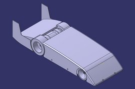
This is the latest CAD model. I have made a couple changes since my last update. I am running an extra 4s pack across the chassis (12s total).

Top view detailing the Castle Creations speed control and Thunder Power batteries. (Blue pack will not be used for the speed run)

This is a detail shot of the great work that
Darren at Aggressive Technologies has done for me. He CNC'd these motor clamps for me. They turned out great. Thanks Darren.

CAD model of the motor clamps.
I have some electronics still waiting to show up. The Neu motor is on the way and should be here by next week. Then I will start bench testing. I'll post my results here.
 Here is the motor. You can see how big this thing is. I am holding a regular 540 motor up next to this monster.
 I am going to have to make modifications to this clamp(the opposite clamp installed perfectly). You can see that there are some red tie-wraps that hold the motor wire to the inside of the can. I did not account for these wires when I was designing the motor clamps. The way it is now, I cannot tighten the one clamp because of these tie wraps. It shouldn't be a problem because I can cut some recesses in the clamp to make room for these tie-wraps.