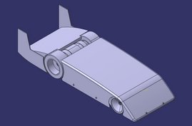
Pictures of the X2 progress in chronological order

Tuesday, October 16, 2007

New wheels and more street testing

Last time out testing at the Houston Dragway, I had problems with my tires holding together at speeds from 60-70mph. I have been working with my father to make some custom aluminum wheels using 1/8 scale on road tires. The wheels I have been using so far are 1/10 scale nitro drag tires:
These tires are very very soft and they are the correct outside diameter (3.25") and width (1.5") for the X2. Since these tires weren't working, I had to go a different route. The 1/8 scale tires are approximately the correct outside diameter (about 75-80mm) but they are much harder foam. The only problem is they are very wide (3"). What I did was to make my own aluminum rims and remove the foam from a 1/8 scale rim. This way I could use the same method of mounting (1/10th scale clamping hub). This is what I started with:


I removed the foam from the 1/8 scale wheel and glued it onto the aluminum rim. Here's what the new wheel looks like (left) compared to the old one(right). The new wheel is much much stronger and should hold up to the extreme forces.

I also modified the front suspension. I moved the tie rods from up above the upper arms to very low to maintain correct front end geometry:

Data from the last street run. Link to the FDR file from my run on 10-11-07. You can view this after downloading and installing the Eagle tree software.

I have also updated my spreadsheet. I added the ability to choose a motor based on what Kv and Kt requirements are calculated. I also added a section where you can calculate the amount of downforce created by a wing added to the car. And based on the traction created by this wing, you can see at what speed your total traction will intersect with your traction needed to accelerate at your desired rate.


Here is the link to download the spreadsheet for use on your own calculations.

Graph showing traction available vs traction needed. The point where the two lines intersect is the speed at which enough downforce will be created to give you the traction to accelerate without spinning the wheels.

I am still working on the wing and how to attach it to my car. Once the wing is completed and attached, I want to get out to the Houston Dragway as soon as I can to do some more high speed testing.

Sunday, October 7, 2007

Road test with modifications for the "X2"

This is the modified steering. The orientation of the servo is unorthodox. I had trouble making sure that I had enough room for the antenna, receiver and switch after the steering had been rotated 180 degrees. Rather than place the servo laying flat on the chassis behind the steering suspension, I stood up the servo and placed it between the steering mounts to create more room for the electronics all the way in the rear of the car.
This is the front end of the car. This is where the pitot tube ports are located. A pitot tube is used on full size aircraft to measure airspeed. The dynamic pressure port is on the bottom. This port measure the forward airspeed as the car is running. The tube on top is for the static port. This measures the ambient pressure. The difference in the dynamic pressure and static pressure is speed. More info on pitot tubes can be found here.


This is where the air travels down the brass tubes to the silicone tubes to the speed sensor. This is where the dynamic and static pressures are measured.
This is data from a short test run I did on the street in front of my house. There is a lot of noise in the data from 0-8 seconds. The car wasn't even running on the ground between 1-8 seconds. After that, you can see from the spikes in the speed data that I made 4 passes. My fastest pass was about 18 mph.

Currently I am working on getting new wheels put together and making a wing for some front end downforce. I will post more about these parts soon.

Monday, September 3, 2007

Update: Modifications

I have been working on changing a couple things for the X2. Since I am driving the car backwards, the front steering (now the back) needs to be turned around to keep the correct steering geometry. I turned the steering around 180 degrees. I also got some trailing front axles to keep excessive twitching of the steering to a minimum. I also changed the caster to -4 degrees.

I got an Eagle Tree Micrologger data acquisition system. This plugs in-between the Thunder Power batteries and Castle HV-110 speed control and can accurately measure a multitude of things. Currently it is measuring battery voltage, current, watts, mAh used, motor rpm and will include the airspeed sensor in the future.

I am also working on machining wheels out of aluminum. As you can see from my previous tests, I am having a hard time keeping the foam on the standard plastic rims. I want to experiment with some machined rims and different foam types to see if I can make a wheel that will hold up to the extreme performance of these speeds.

I am also working on a setup to provide downforce on the front wheels. My lack of acceleration is due to the fact that the coefficient of friction is lower than I expected. One way to increase traction without changing foam compound and increasing the weight of the car is to increase the downforce.
Here is a shot of the front suspension. It has been reversed to obtain the correct geometry. I installed trailing axle steering blocks to minimize the steering reaction. I also removed 1 set of washer from underneath the suspension arm mounts to increase the rear ride height to approximately 8mm. The upper arm mount shims were moved to provide -4 degrees of caster.
This is the Eagle Tree data acquisition micrologger. This will help me accuratley monitor voltage, speed, motor rpm and amp draw.
This is a sample graph of what the Micrologger can do. This example was from a quick bench test to see if everything was working. The car was freewheeling on the car stand. There seems to be some noise in the data. The only time the wheels were running is when you can see the rpm move into the 2 "humps" on the bottom of the graph. I was throttling up slowly to neutral then slowing down again. I did this twice. The data right before and after These rpm "humps" shouldnt be there since the motor wasnt even rotating. This could be caused by cogging of the brushless motor. You can see the rpm shoots up to 50,000 then goes to 0, which shouldn't happen.
Wheels being machined

Saturday, August 18, 2007

New website

Updates on my car will continue to be at this website. The new website where I will keep all other fast RC cars will be at www.fastestrc.blogspot.com

I'm updating the site

I am going to make some big changes with my website. I started this website to keep a detailed record of all the fast RC car projects people are in progress. I also wanted to keep a detailed report of all the high speed events and have all that info in one place. But when I started on my project "X2" and detailing all of my progress, people were getting confused on who was making what car. For example, when Jalopnik reported on my car, they thought it was Nic Case who was making it:

Most full sized vehicles can't hit 200 mph, let alone radio controlled cars (in actual miles per hour, not scale). But Nic Case hopes his X2, currently in development, will do just that. Current holder of RC car speed record of 134.4 mph, Nic's goal is nevertheless an optimistic one. Powered by a 29.6 Volt direct drive motor, the X2's theoretical top speed is 274 mph, but that's without any drag generated by friction with the road or air. Special foam tires capable of withstanding the incredibly high RPMs keep the diminutive car in contact with the track, while a gyroscope manipulates rudders to automatically keep it in a straight line. A video of the X2 running shakedown tests follows the jump.

So after reading this, I am going to change the website to show just my updates for my car. I will move all the other posts to a new website.