These tires are very very soft and they are the correct outside diameter (3.25") and width (1.5") for the X2. Since these tires weren't working, I had to go a different route. The 1/8 scale tires are approximately the correct outside diameter (about 75-80mm) but they are much harder foam. The only problem is they are very wide (3"). What I did was to make my own aluminum rims and remove the foam from a 1/8 scale rim. This way I could use the same method of mounting (1/10th scale clamping hub). This is what I started with:
 I removed the foam from the 1/8 scale wheel and glued it onto the aluminum rim. Here's what the new wheel looks like (left) compared to the old one(right). The new wheel is much much stronger and should hold up to the extreme forces.
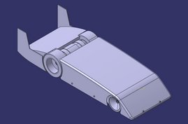
 I also modified the front suspension. I moved the tie rods from up above the upper arms to very low to maintain correct front end geometry:
 Data from the last street run. Link to the FDR file from my run on 10-11-07. You can view this after downloading and installing the Eagle tree software.
I have also updated my spreadsheet. I added the ability to choose a motor based on what Kv and Kt requirements are calculated. I also added a section where you can calculate the amount of downforce created by a wing added to the car. And based on the traction created by this wing, you can see at what speed your total traction will intersect with your traction needed to accelerate at your desired rate.

Here is the link to download the spreadsheet for use on your own calculations.
 Graph showing traction available vs traction needed. The point where the two lines intersect is the speed at which enough downforce will be created to give you the traction to accelerate without spinning the wheels.
I am still working on the wing and how to attach it to my car. Once the wing is completed and attached, I want to get out to the Houston Dragway as soon as I can to do some more high speed testing.