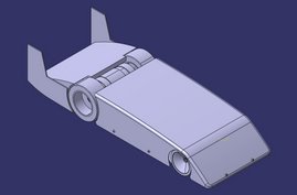
Pictures of the X2 progress in chronological order

Thursday, January 17, 2008

Boycott Dymond


It has come to my attention that Helmut Goestl of Dymond Modelsport has a class action lawsuit against Castle Creations and Thunder Power batteries.


These two great companies, Thunder Power and Castle Creations are my sponsors. The have supplied me with components that work flawlessly during my testing.

The class action suit has to do with Mr. Goestl saying that Castle Creations products and Thunder Power products aren't made in the USA. They represent the best of American technology. I support Castle and Thunder Power 100%. Please do Castle Creations, Thunder Power and myself a favor and boycott Dymond Modelsport and anything Mr. Goestl is associated with. Read the links in this article to get the whole story. Thanks for everyone's support.

Thursday, December 27, 2007

New wheels installed, "X2" ready for high speed testing

"X2" with new wheels installed

These new wheels are now the correct diameter and trued for high speed running.

New wheel on the left, old wheel on the right. You can see there is much less sidewall of foam. Hopefully this will reduce the likelihood that the foam will fly off the rim. The new aluminum wheels are much heavier than the plastic ones, but they are much stronger.

Data from a slow speed test using new wheels. High speed for this run about 28 mph.

Weight of "X2" with all electronics installed except for the body, 6 lbs 8 oz.

Tuesday, December 11, 2007

More wheel designs

All wheel designs to be tested in the next high speed run.

On the left is the 1/8 scale on road based wheel and on the right is a much larger OFNA style on road wheel. The OFNA based wheel has a much larger inside diameter and outside diameter. The idea with the OFNA based wheel is to minimize the sidewall size of the wheel while keeping the outside diameter close to 3.25". The tire needs to be trued down to correct size. You can also see that a hub isn't used to attach the wheel to the motor shaft. Instead a mount using setscrews is used to tighten the wheel on the motor shaft.

Friday, November 16, 2007

Wing design

From my initial calculations, I need to get downforce on the front drive wheels in order to get enough traction to be able to accelerate at an acceptable rate. I am starting the wing design using a symmetric airfoil (NACA 0006). Ideally, I want to be able to create a significant amount of downforce at low speeds, then decrease downforce coefficient at higher speeds. I do not want to create too much downforce at high speeds. This will put unnecessary strain on the car and will increase drag significantly. The goal is to keep enough downforce on the drive wheels to create enough traction to get up to speed quickly. The idea is to have a flap that will start off at a large angle (60 degrees) then decrease angle as the speeds increase. This will lower the lift coefficient (downforce coefficient in my case), but maintain a certain downforce on the drive wheels throughout the speed range of the car.

This is a rough mock up of how the wing will be placed on the car. Because the wing is so close to the ground, ground effect will increase the wings effective downforce coefficient.

Profile view of the NACA 0006 airfoil showing different degrees of flap.

Series of pictures illustrating how the flap will decrease in angle as speed increases:

Tuesday, November 13, 2007

More wheels and transmitter modifications

Latest iteration of the "X2"
Wheels

Still working on more custom wheels. I want to try out a number of different wheels to see which ones will work best. I already have two types that I want to try. Each wheel has a different foam thickness.

Wheel being measured for roundness.

Transmitter

I had just about given up on my 3PM transmitter until I found out that increasing the range on my Futaba 3PM 2.4 ghz transmitter isn't very difficult. There are a couple of off the shelf components that I found to increase range. Since 2.4 ghz is widely used in wireless internet, there are many places that sell components such as pig tails and amplifiers. I was able to open up my 3PM and see what kind of connectors were used for the antenna. Then I was able to find a 500mW amplifier to significantly increase my range. This is what the transmitter looks like with the modification:

Futaba 3PM 2.4 Ghz modified to increase range. Range of the stock transmitter is a measly 300ft. With this 500mW amp I have increased the range by about 3x.

Parts used:

Pig-Tail (U.FL to RP-SMA):

500mW Amplifier (RP-SMA):
Gyro:

I included a gryo into my setup. I found out that after I corrected the steering, the car had become much more sensitive with steering input. I tried all the adjustments to minimize this and nothing seemed to work. A number of people have said a gyro helps significantly. This gyro is nice because I can use the third channel on my transmitter to increase or decrease the sensitivity of the gyro without stopping the car to adjust the gyro itself. I can adjust it remotely.

Matt Shumaker described how a gyro affected his car. He has noted that at low speeds the gryo helps significantly by keeping the car on a straight trajectory with much less steering input from the driver. But at high speeds, the gyro makes the car feel numb. This is especially true if the gyro is too slow to compensate for movements in the steering.

Futaba GY401 next to the right rear wheel in the "X2"
Front end displaying the Thunder Power batteries and Castle Creations HV-110 performing perfectly during all of my testing.

I am still working on a wing to create downforce. The tight spaces on my car limit where I can mount a wing. I am now sizing the wing and airfoil section to create the desired amount of downforce at a certain speed.